Tuesday, July 28, 2009

Foot Hoses

I got the final parts I needed to finish in the mail from Resinparts.com. Among them were the knurled fittings for the hose ends on the feet. I prepped and primed those last night, put a couple of coats of metallic silver paint on them today, and then I epoxied the braided hoses I got from the club into them. I bought a piece of 3/8" OD poly tubing at the hardware store to go inside of them and hold the shape of the hoses. And I cut the hoses to 14". That's 12" to show and an inch inside of each knurled fitting:


I also laid out and drilled the holes for the fittings into the foot strips for the front outer feet. They are in the corner of the picture above. If you don't have one of these, get one:


It's a stepped drill bit and it is really effective for cutting big diameter holes. The steps mean that it doesn't have to remove so much material as it goes. Much faster.

Then I laid out the holes on the foot shells, took a deep breath, and drilled some big craters in them. Like Norm Abrams says, measure twice, cut once. But I usually measure 3 or 4 times, and still have to calm myself before cutting into a piece that I have been working on for months. But they came out fine:


I also laid out and drilled the mounting holes in the battery boxes. I thought I had a picture, but I can't find it now. But I can find this killer picture of a bad ass alpha male gorilla from the San Francisco zoo instead:


When I drilled the holes into the battery boxes I discovered something that will be relevant to folks who have bought them from me. The thickness of the curved wall is about 1/4", so when you cut that 5/8" hole in the face, the wall inside impinges a bit into where the sleeve on the knurled fittings goes. That is, you can drill the face hole fine, but inside there's some interference because the side walls are thick. Don't try to ream that our with the drill bit; you'll just chew up the face hole and make it too big. Use a dremel tool with a small grinding bit and go inside and ream out enough material to make room for the knurled fitting. It took me about 5 minutes to clear it so that the fitting would sit right on the battery box.


And here's the result with the hoses rough fit into the foot shells and battery boxes. I'm not going to glue them in until I think about it for a day or so. I can get some nuts to thread onto the fittings inside the foot shells, I think. But I don't know how functional the threads on the resin fittings are. But I think I'll epoxy the battery box end of the hoses in.

Sunday, July 26, 2009

Body Details


Lots of little details to work on. But that's a relief after the huge assembly of the body and legs. I bought some 1" by 1/8" aluminum stock a while back with the intention of using it for the foot strips. I cut the strips, laid out the measurements, and put the beveled ends on them for the three feet.

I've been puzzling over attachment for the a while, though. I don't want to just glue them to the foot shells. It would work, but it would be semi-permanent and I wouldn't be able to paint the shells again if I want. And I have it in the back of my mind that I'll repaint these shells shortly because of the clear coat fiasco. I'll probably strip the clear coat off, rough them up a bit, and then put gloss white on them to match the body.

So I thought I might be able to cut some pieces of threaded rod, mount them on the back of the strips, drill holes in the shells, and then put nuts on the inside to hold them in place. I drilled shallow holes (not all the way through!) on the back and tried to use JB Weld to glue these in place. It didn't work too well. If you clean the lump of JB Weld away from the base to they fit down tight on the shells, there's not enough epoxy to really grab and then come off. I'm still working on it. Here's pictures of them in place:


I spent some time the last few days building these frame mounts for the utility arms to go inside the frame. Here are the pieces of the design I settled on:


Assembled, it looks like this:


And then mounted inside the frame it looks like this:


The real trick of it, obviously, was getting all of the measurements exactly right so that the utility arm sits flush to the outer skin on the outside, and lined up vertically and horizontally just right with the utility arm shaped hole in the skins. That took some work, and I did a couple of tries before I got them right. A virtue of this design is that the back plate that screws into the inside of the frame above and below the slot for the utility arm can be slide right or left until the placement is just right, then I could drill pilot holes and put the screws in.

Once I got them in, I drilled another pilot hole into the bracket from the front and put a screw into it. This acts as a stop for the utility arm to keep it from swinging into the body. I can adjust the screw in or out to get the utility arm to sit exactly flush with the skins. I thought that was clever. Seems to work well:


I also took a piece of expanded cell PVC board, like I used on the battery boxes, to make an inside wall piece so that it's a closed chamber behind the utility arms. (It's not in these pictures.) I heated it up with a heat gun and bent it to fit flush inside the inner wall of the frame. So it screws right on over these brackets on the inside and gives the utility arms a finished look from the outside. I thought heating it up for the curve was clever. I tried to do it with a curved piece of wood but it was too bulky and heavy.

Monday, July 20, 2009

More Pictures: Legs and Body


Body and Legs: Painting and Assembly

I've put in a lot of work on the droid lately. Mostly painting and assembly. Here are a few pictures:


The painting has been hard. I got good results on the body with the Rustoleum Satin White that the club recommends, but when I put clear coat on it, it came out terribly. Lots of runs and rough spots. I've tried a couple of different kinds of clear coat now in several different conditions and it has never come out nice or clean. I'm not sure what I'm doing wrong. I've tried to control for humidity, heat, thickness of coat, etc. But no matter--it still looks like crap. So I stripped the clear coat off of the body and switched to gloss white. That gave me good reliable results.

The club method for R2 blue has been mixed. I have gotten it to come out really rich and deep blue and it looks like it has that depth that it is supposed to, but it's been hard to do that consistently. I've sanded several parts and started over. Again the clear coat has been finicky.

I tried several different kinds of metallic aluminum, chrome, and silver paint, trying to get the one that looked the best and looked most like raw aluminum. I finally settled on a Rustoleum metalized silver. The color's good but it doesn't seem to be very durable. Have to figure out the clear coat problem.

Assembly went pretty well since I did so much dry fitting of everything before painting. I started trying to mount the assembled pieces on the body with styrene solvent cement after I had cleaned the mating surfaces, but a gel super glue worked much better. Gives good control and very little seepage, and it doesn't seem to eat up the paint.

I'm working on the remained body components now: front vents, surrounds, utility arms, ankle details, etc. I'm going to try to make some of those by hand instead of going with resin or aluminum. Looking ahead to the electronic system and trying to plan the lights, motors, motor mounts, and sound system. There are a lot of decisions and lots of research.

Tuesday, June 23, 2009

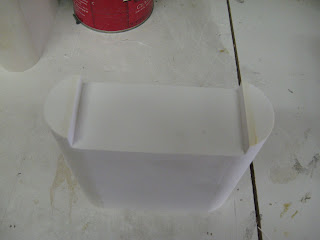
Battery Boxes for Sale, Council Approved.


I have just completed my 3rd run of Battery Boxes. I've got 12 pairs to sell.

Construction: The side walls, top and bottom are made of expanded cell PVC sheet (1/4” and 1/8"). The end pieces are made of PVC pipe, sliced in half. All joints are glued heavily with PVC cement. They are sturdy enough to stand on.

I have not put any holes in the front for the cables or the sides for mounting to the feet. If you are putting motors inside of them, the PVC is easy to work with. You'll have to check to see which motors are compatible with the 1/4" sidewalls and the reduced width of 2.9". I haven't installed NPC motors in these, but some of the previous buyers probably have at this point. I can check.

Specs: These boxes are to club specifications with one exception. The width of the boxes is about .1" shy of the 3.00" blueprints. PVC pipe with an exact 3" outside diameter is difficult, if not impossible to find.


Finishing: The boxes have been finish sanded down to 320 grit. All the joints are smooth and clean. They are almost ready for primer. They may need a bit of touch up sanding here or there.

Price: $85 a pair plus shipping. Email me at mccormick@csus.edu for exact shipping costs, and paypal that email address to place your order. I should be able to get them shipped out with a day or two of getting the order.


Sunday, June 14, 2009

RoboGames--R2D2


Went to the RoboGames in San Francisco today (and the Maker Fair a few weeks back), and hung out with Chris James for a good while. His droid is an amazing piece of work, and his blog has been a huge source of helpful information to me from the start. It was great to get a close up look at it. Chris got me and my boy, Max, into the pit area at the RoboGames by assuring the event staff repeatedly that we were with him. And he even handed me the remote control to drive his R2 around a few times. That showed some trust. I know every bit of agonizing work that has gone into his machine, so I took it very easy.

One Year Progress Report


Despite the lack of activity here on the blog, I've been working on it quite a bit lately. I got the styrene skins all glued on. Getting the inner skin attached to the frame is tricky. Turns out that even though lots of materials experts have opinions about the best adhesive for styrene to wood, none of them seem to know what they're talking about. I bought 15 or 20 different kinds of glue, ran extensive tests on all of them until I found something called Griptonite by Devcon. It's more or less a superglue, but it is a bit thicker than most, and there's something in it that dissolves the styrene a bit to make it bond well. I bought up every tube within a 50 mile radius--TAP Plastics, and attached the inner skin bit by bit. Alignment and drying times were hard, but I got it figured out with some work. Then I got the outer layers glued on. Here I could use standard styrene cement--Testors--and it works fine. The results are good. Here's the whole droid, more or less with a lot of the major assemblies fitted on. I have lots more parts on the bench, but I'm not ready to mount them.

I've also got my Rockler bearing mounted here with the dome ring loose mounted. Lots more work to do. More later.