Sunday, October 26, 2008

Battery Boxes for Sale


On the last small run of Battery Boxes I did, there was a huge amount of interest. I sold 5 pairs in less than an hour. So I have done another, bigger run. I’ve got 12 pairs to sell.

Construction: The side walls, top and bottom are made of expanded cell PVC sheet (1/4”). The end pieces are made of PVC pipe, sliced in half. All joints are glued heavily with PVC cement. They are sturdy enough to stand on.

I have not put any holes in the front for the cables or the sides for mounting to the feet. If you are putting motors inside of them, cutting a hole in them and mounting them shouldn’t be a problem. But I don't know if different motors will be compatible with the 1/4" sidewalls and the reduced width of 2.9". These have not been tested for NPC motors.

Specs: These boxes are to club specifications with one exception. The width of the boxes is about .1" shy of the 3.00" blueprints. PVC pipe with an exact 3" outside diameter is difficult, if not impossible to find.

The inside dimensions are 1/2" smaller than the outside.

Finishing: The boxes have been finish sanded down to 320 grit. All the joints are smooth and clean. They are almost ready for primer. They may need a bit of touch up sanding here or there.

Price: $85 a pair plus shipping. Email me at mccormick@csus.edu for exact shipping costs, and paypal that email address to place your order. I should be able to get them shipped out with a day or two of getting the order.


Monday, October 13, 2008

Ankle Tubes and Shoulder Update


Here are the little tube things that go on each side of the center ankle and on the outer ankles. It took a couple of tries to get them just right, and I am still not perfectly happy with them. But I think once they are painted they'll be fine. I cut 1 inch (inside diameter) pvc pipe to length. Then I cut little squares of 1/8" pvc sheet to glue to the ends. I glued those and let them sit for a few days. PVC cement gets a lot harder if you let it cure for a while. If you sand it too soon, it'll be more flexible and soft than the surrounding material and you'll sand it out of the joint and make a groove.

Once those were cured. I used the sander to round the square pieces down to match the round edge of the pipe. This wasn't a very reliable method for getting them to perfect circles. But I couldn't think of another method that would leave me with no seams.

The little channels that are cut into the circumference of these pipes are supposed to be .03 " wide or so. My table saw blade is .1 so that was too much. My bandsaw blade was just right. I figured out the depth of the channels and put a stop on the crosscutting slider on the bandsaw so that it would stop the piece just after the blade began to cut the pipe. Then I would carefully roll the pipe into the saw blade, keeping the slider still. So it cut a groove all the way around the pipe. This was a reliable and good method with good results. It just took 15 minutes to cut all four pieces and a spare. Then I cut the little hexagonal end caps for the tubes and glued them on. A little more sanding and these will be ready to go.


Here are a couple of pictures of the finished shoulders. I'm pretty happy with these. In an earlier post I detailed how I built up the plywood pattern for these that would guide the router roller bearing as I cut them. I cut all 16 or so pieces, and glued them all together in stacks to make these ribbed assemblies. Then I sanded the outside edges down to clean them up. I spend some time putting putty on the insides of the interior pockets, as you can see, and then routing those on the forms again to clean them up. This wasn't the perfect method. If i was doing these again, I wouldn't cut the interior pockets out at all when I was cutting the individual layers. I would wait until the whole assemblies were glued up and then I would drill a hole in the middle of the pockets, and then rout that out once and all at once. Make sense? That is, instead of routing these pockets out 16 times on each individual layer piece, I would glue them all together and rout them once. Then I'd get really clean aligned inside edges. And there wouldn't be the need for putty. But I think these will clean up for paint just fine. The three dowel holes will get filled later. And I think I'll put some dowels sticking down into the legs for attachments.

Saturday, October 11, 2008

Battery Boxes for Sale


I've got R2D2 Battery Boxes for sale. I have 4 extra pairs. They are constructed from PVC. They are rough sanded and just about ready for primer. They may need a small bit of filler, and some spot sanding. They are to club specs with one minor exception:

Full Disclosure: The boxes are 2.87 inches wide instead of the called for 3.00 inches. PVC pipe with an outside diameter of 3 inches is very difficult to get in the US. But the difference would only by noticeable to someone with calipers and a copy of the blueprints.

They are $75 a pair, plus shipping. I can have the boxed and shipped very quickly. Paypal my email: mccormick@csus.edu. Send me an email with any questions.

Here's a couple more pictures:


Saturday, October 4, 2008

Vacuum Table


I can't see that I'll need a vacuum table, but I might for this project. But my brother is building Snow Trooper armor. So I put this vacuum forming table together for him today. We'll test it out soon.

Monday, September 22, 2008

Shoulders

The last couple of days were spent almost entirely building these:


Here's the idea. The shoulder call for stacks of 8 1/8" pieces with some details and tight tolerances. I bought a sheet of PVC--$50 or so, which is a lot. But I didn't want to do this part in MDF. I think the plastic will give a better, more durable result, especially on the cut edges.

These templates I made by printing up the PDF files in the blueprints to full size. Then I sprayed on some adhesive to 3/4" plywood and laid the plans down on them. The left and right shoulders are mirror images of each other on the cut out details, so I am just going to reverse the template for the other side (I hope I remember to do that when the time comes.)
I worked pretty hard to get all of these cuts just right--there's only an 1/8" difference on the edge alignments. I cut the outside straight edges on the table saw with the fence. That let me get good straight cuts and to carefully control the overall width. To get the rounded curve on the top, I screwed the templates together and sanded them on the 90 degree table on the belt sander. That way they will match.

The inside curve--the round part on the top inside of the horseshoes--proved to be hard to cut. I tried the bandsaw, but mine won't cut curves with that tight of a raidus (3.39" diameter, I think.). Finally I built a little circle cutting jig on my router table. I mounted a piece of plywood over the table, put in a small, straight cutting bit, and them measured from the edge of the bit to the pivot point. I put a pin there, and drilled the exact center of my horseshoe template blanks to accept it. Then cutting the circle was clean and had good results. I think I got well within .005" of the club plans. That's good enough for me.

I've spent the last few days routing, chiseling, and filling in the square cutouts on the sides of the horseshoes. My router chewed up the pieces a bit, so you can see some bondo drying in the boxes here. That'll sand up cleanly.

You can also see some dowel pegs mounted on the templates. I got that idea from Vic Franco. Those will accept my PVC sheets, holding them, while I rout around the template with a flush trim bit. I tried a test piece and the results were very clean, and easy. So I cut a stack of blanks--16 for both shoulders and a few extra--and drilled them to match`the three holes for the dowel mounts. When the templates are done, I'll start cutting and stacking pieces.

Booster Covers


If I had any sense, I'd buy the booster covers in resin for $60 and save myself the work and expense. As it is, I spent a good bit more than that getting a couple of router bits and things to build them myself. But clearly, building your own R2 model isn't about having any sense. So I tackled building the booster covers myself. And I enjoyed it for the most part.

I broke the assembly up into pieces that I figured could be easily cut, finished, and machined. So I made up the legs and the main body piece. And I attached the legs at the end using a separate cross piece. This beats trying to build two legs attached by the small piece at the top all at once. I knew that getting inside to make that little router cut would be hard.

I cut blanks for all piece out of 1/2" fiberboard--again this stuff sucks because of the dust it creates and the cancer it causes. If I did this again I think I'd try to do it in plastic--maybe PVC, although that would be costly.


Once I had the blanks glued up (you can get the fiberboard/MDF in thicker sheets, but this is what I had, and the glue up isn't hard once you get the hang of it), it wasn't very hard to first, cut the bevel cut across the top of them--53 degrees I think, and then I set up the router table to trim that bit out of the inside tops of the legs.


Here's the bigger blank that I made for the thicker top assemblies. The thing looks really complicated on the plans, but it all starts with a simple rectangle. I made extras of both here because it's easy when you're tooled up to crank out another one, and I've learned that having a few extras gives you some breathing room and space for mistakes. I find that when I'm doing a new bit like this, my technique get a lot better after the first one.

Next up, I set up the router with an itty bitty round groove bit, set the fence at the right distance, and set up a stop block on the fence to make sure that I got all of them the same length. Then I ran the legs into the router and put this cute little channels into the bottoms. Pretty easy compared to some stuff so far. The channel groove that goes around the legs horizontally above the vertical round grooves isn't hard with the table saw. I checked my main leg assemblies to make sure that the groove on the legs lines up with the groove on them. Vic Franco said that some of the resin booster covers can heat up and warp out of alignment in the curing process and not line up here.


That smear on the left leg, as far as I can tell, is chocolate ice cream from my two year old who was investigating the work bench. I am hoping it will cover over with paint. When he sees the pieces laying around he shouts, "Doo-Deet, Doo-Deet!" It's pretty cute.


Next up I went to work on the top section of the booster covers. Here you can see the funky curve sanded into the top, the side bevels on the curve, and the pockets in the bottom of the block. Here's what I did. The bevel cuts on the top weren't hard. I measured them off according to the plans, and then I cut them with the bandsaw and sanded them (If memory serves.). Then I marked off the curves on the front and back. The curve is beveled--that is, it doesn't cut through at a 90 degree angle from the front face. I think that some people out there have done this part by using a sanding drum on their drill presses and tilting the table on the drill press. That's a simple and elegant solution. As it turns out, the drum on the end of my belt sander was almost exactly the right diameter for this. So I got the curves marked on the front and back and I very slowly sanded away the material until it matched those lines. Not hard.

I made pockets again by cutting all the way through the block with the router table. I think it's a .3" bit or thereabouts and set to .75" depth. Then I cut some replacement blocks to squeeze down into the channel and leave only the two pockets. Next I'll rout the cove out of this bottom face. The plans call for a 5/8" cove. Bits in that size are hard to find. You can order one, but they are $50 or so. I opted for a 1/2" cove bit which is much cheaper and easier to find. Then I think I'll use a 1 1/4" dowel and some sand paper to remove material to get it to spec. If that proves tedious--and I have a very low threshold for hand sanding tedium--I'll bail and leave it at 1/2" diameter, I think. If anyone has better ideas, I'm all ears.


And here's the whole thing so far laid out, along with the little triangular dog house pieces that sit on top. I made those in box form with 1/4" MDF and then cut and sanded them down to size. It'll take some trimming and detail work to get all of this assembled. But it's close to being done.

Outer Feet Details, Finishing, and Primer


Next step was to fashion the little detail panels that mount along with the half moons on the foot shells. Like many of the other details, I could have bought these. But they were really easy to make. Again I used 1/8" expanded cell PVC sheet, cut the pieces, sanded them a bit, and then mounted them with PVC cement. I did some sanding here and there, a little trimming, and filled a few gaps with some putty, then put on a coat of primer. The results are really starting to look like R2. I'm happy with the feet, and I am happy with the difficult task of getting those bottom skirts with the slots done right. I'll be setting these aside for a while until it's time for more painting.


More Foot Details


The half moons for the feet presented a bit of a dilemma. On the plans, and sort of evident in pictures of the real R2, the little square raised panel on the outside of the half moon has a taper so that it gets slimmer towards the top--where the two horizontal slots are. In practice it turned out to be very hard to produce a piece like this in my shop. You'd think it would be easy, but the damn thing is 2" x 2.5" inches, I think, by 1/8" thick at the bottom (going from memory). So that's a pretty little piece to be machining, sanding, grinding, or trimming. I tried several ideas for it. I built a little sanding jig that might let me grind it evenly off. But nothing worked. The plastic I was using melted. I might have been able to do it with fiberboard--but I wanted to make this parts all plastic. And that fiberboard when you sand it puts loads of tiny particles in the air and a big label on it says that the State of California knows it to be carcinogenic. I've breathed enough dangerous fine particulate matter in my life.

So I abandoned the plan to taper it and just used the piece and full thickness all the way up. Maybe that doesn't seem like a big deal, and I don't think it will show much. someone would have to really know what to look for and maybe bust out the calipers to see the problem. But that's the first time on this whole project that I have deliberately punted on some problem because it was too hard--makes me feel like a baby just saying it. "Suck it up, you baby, and MAKE THAT PIECE RIGHT!"

Not really a big deal.

So then I hatched a plan to put those little 1/8" slots across the panels. I set up my router table, ran some test pieces, and just ran the whole half moon piece through, cutting through the edges of the rectangular pattern where it's supposed to be solid. Then I cut some tiny little replacement pieces and glued them back in. You can see them in this picture. But once I've trimmed them, and sanded them a bit, and then painted, they won't show. That "cutting through" trick has made a several little recessed slots on this project much easier than they would have been.

Outer Feet Door Channel: hard


Lots of progress in the last few weeks. Here's a shot of one of the outer feet and the channel that I routed in it. I used a method like I used in the earlier post on the center foot. I must say that thus far, setting up this cut and pulling it off was one of the hardest things I've done. Building the template took a lot of work and a lot of fine tuning, and then actually cutting the channel was rough. The ABS plastic that I had used for the foot shells is really prone to overheat and gum up on any sort of power cutting tools. So getting a clean cut that didn't jump the tracks at all was very tricky. If you look close you can see some hitches in the cut, but it turns out that they cleaned up with some bondo pretty well. So I am content with the result.

After thinking about it a lot, I opted to not cut the panels all the way through. I like the clean smooth look that this leaves instead of having all the alignment problems that reattaching a door would cause. I routed the channel 1/8" deep in 1/4" walls. I may change my mind later, but I can't see that having the door come off is going to be that helpful with the foot motors later in ways that getting to the motors from underneath won't be. I'll try to build the motors with this in mind.

After browsing through the tool store the other day, I realized that there are some small router cutting guides that insert into the bottom plate and that can be used on a template like I have done here. But the difference is that the cutting guides can be used on a template that is much smaller. I made my templates to fit the whole bottom plate of my router. I don't know if using the guides would help. My routing skills and my routing patience are slowly getting better. But I still think it is crumby tool. Too hard to control. It feels like trying to get the Tasmanian devil to behave to cut a perfect straight line.

Monday, September 1, 2008

Access Plates on the Feet


Check this ILM R2 picture: Here's the biggest challenge I have for the last couple of weeks. On all of the feet, there are access panels cut out in trapezoids on the sides.

Some people cut these out with Dremel tools, I guess. I tried and tried but could not find a reliable, or effective way to do this with a Dremel. I guarantee that if you try to freehand this channel, you will not be able to stay in the lines and you'll end up with a butchered piece. So I have been puzzling over how to set up some kind of jig to do this cleanly.

My other challenge was that I don't want to cut all the way through on this. I don't see the need, and too many of these doors look like crap when people try to get them fastened back on. Even the ILM R2 looks like hell.

And while I'm on the subject, have you noticed how completely beat to shit all of these real R2s are? What did they do, kick them down the stairs? I guess that's just the wear and tear of 25 years in some cases and the abuses of a movie set, but jeez. It's making me cringe looking at the chipped paint job, dents, and all. And it kind of seems like they did a crumby job on the paint. I guess there aren't any shots in the movies that scrutinize them as closely as we're doing here.

So here's my clever ( or at least I think it is clever) solution. I carefully drew up the foot side wall on a piece of 1/4" hard board. When the 1/8" bit is in there, the edge of the my router plate is 2.82 inches out. So to rout the channel, I needed a template that was 2.82 inches bigger in all dimensions than the actual size of the channel. So I drew that onto the hardboard around the drawing of the side. Then I cut that out. And notice in this picture that to get the router bit to turn the .625 " radius curve in the corners of the channel, I had to draw a .625 + 2.82" radius curve.


Once I had that bigger trapezoid with curved corners drawn, I cut it out on the bandsaw (to cut an interior piece out like this I just cut through the edge--it won't matter on the finished template. Then I glued that cut out piece onto another piece of hardboard. So there's a lip for the router plate to rest against and when you run the router around it, the cut comes out to be exactly the shape of the channel. Cool huh?

I carefully screwed the template directly onto the sides of the center foot, took a deep breath and checked everything again, and then router out the channel. I'm pretty happy with the results:


There's one flat spot on the lower right corner, but I think I know how to fix that by smoothing out the curve on the template. Given how hard this cut is, I am happy with the results. Now that I know how to do it, I'll cut out a similar template for the channel on the outsides of the outer feet. Once the hole is cut, but before I attach it to another piece of hardboard, I can run a file around the inside edge and make a nice smooth surface for the router plate to glide along. Once these surfaces are sanded, primed, and painted, I think the results will be really nice.

Foot Details

Next I got to work on the details for the feet. Building the half moon pieces for the sides of the feet was a pleasure and went pretty easily. I could have ordered these in resin, but there's no fun in that. And I have a clever solution for you DIY people. These need to be 1 to 1.5 inches thick, roughly. I didn't have any plastic that thick. So I cut out several matching rectangles of 1/4" expanded cell PVC that I had. This stuff works much easier than the ABS. My only worry was the slightly grainy texture that cut edges have. The surface on this stuff is slick and clean, but the core is--as the name suggests--full of tiny bubbles that make it a little rough. These worries turned out to be ill founded, I think. More on that in a second.

So I glued 4 and 6 layer stacks together with some plastic glue I had. It was a watery kind labeled for Acrylic, but the dude at the warehouse assured me that it would work on the PVC too. Turns out it will work, but you really have to flood the surfaces (both of them) to get it to start chemically breaking down the plastic and make for a good bond between the layers.

Once I had those stacks dried, I cut them into a couple of exactly square 7 x 7" pieces. I laid those out with the circles--I can't recall the exact dimension. But I knew that I was going to be slicing my circles into half moons, so I made them bigger to account for the .1" saw blade cut out of the middle. I rough cut those half moons on the bandsaw, and the finished them down to (nearly) perfect semi-circles on the sander. I'm getting better at doing this. And this method rough cutting close on the bandsaw and then finishing on the sander is working well. My sander, as I have said before, can tilt up to 90 degrees so I can put pieces on the table and then run their edges onto the belt, kind of like a jointer.

So I sanded four pieces down to half moons that fit the blueprints. But then how to get then sliced off like wedges of an orange so that they would sit right on the sides of the angled feet? I played around with the tilting table and the fences on my bandsaw and tested several pieces until I got the angle and the cut right, and then sliced them down to make orange wedges.


I don't know if the written description can make sense of it, but the picture shows the result. With many of these steps, you don't really understand the piece or how it works with the R2 overall until you actually get in there are start trying to build it. Then you get intimately familiar with it. So if you are trying to make the half moons, dive in and email me too.

The next trick on these is going to be fashioning a 2" by 2.5" by .125 (or so) rectangle that mounts right on the outside. Look at this picture of an ILM R2:


The tricky part about this rectangle is that it tapers in thickness from .125 (if I remember right) down at the bottom, to almost nothing at the top where it meets the curve and has those two routed slots in it. Making the piece is easy, figuring out a way to cleanly remove material to make the taper has got me stumped. You can't just rub this thing on sandpaper, unless you want to spend an hour on each of 4 pieces. As usual, I want a repeatable, power tool solution to the problem. Right now I am thinking of building some sort of little jig that will allow me to sand or cut the pieces consistently and quickly.

Feet


I have been very busy on the feet lately. There has been some frustration and some success.

I pondered my choice of materials for a long time. As I see it, one could build the feet from aluminum--either welded or JB welded like Dan Baker's, or steel with spot welding, or wood, or plastic. After much back and forth, I settled on plastic. I liked what I saw on Victor Franco's blog about their feet, and the PVC looked like it was good to work with.

When I got to Interstate Plastics, it looked like ABS plastic in 1/4" was as stiff and just as good for my purposes and cheaper, so I bought a sheet of that. It was cheap--maybe $50 --can't remember.

It turns out that ABS--and I should have foreseen this--has a pretty low melting point and it smears and gums up when you saw or sand it if you don't do it just right. Very touchy stuff. If I had really thought it through, I would have seen that because ABS is the same stuff, in thinner sheets, that they use to do vacuum forming. There you heat up a sheet on a frame, force it down over a positive mold, suck the air out and let it cool. My brother's working on a snow trooper this way.

But after some fiddling around, I got the hang of it. And I have to say that all of the trapezoids with compound angles on the feet are really complicated. I botched a few and worked on it for a while, but in the end I got the pretty tight clean joints I wanted.

That's a piece of 3" (inside diameter) PVC cut into quarters that I used for the inside curve that goes under the battery boxes. Also notice that I put the edges of the pieces exposed on the outside--on the channel for the legs for instance, so that I could get to them and sand them easily.

By far, the trickiest parts were getting the bottom skirts right.


Some people seem to have left these off of there R2s, or they have not included the lip that is underneath the strip with the rectangular cutouts, or otherwise altered the plans. I was pretty determined to get this part as close to spec as I could. Eventually, after making piles of scrapped, failed attempts, I cut strips with bevels on both edges, then I carefully glued up a rectangle that was .08 narrower than the tops of the feet. That way, when I glued on the strips with the rectangle cutouts, the pieces would line up with the tops. Sorry I don't have pictures of these steps--my wife cleared the camera. After a lot of sanding and gluing, I was able to more or less accurately join the bottom skirts with the top trapezoids. In the picture you're seeing them before sanding, filling, or repairing. In general I want to get as much done with the saw and the cutting so that I don't have to do a lot of hacking, carving, puttying, and sanding latter. Sanding is dehumanizing, even with my killer 220 volt, 6" x 48" belt sander. I think that with some more work, these will clean up and look nice.

Sunday, August 24, 2008

The Big Day


It's a very important day in every boy's life when he gets his dome:


Lots of work to be done on it. I'm starting to review everyone's blogs about the steps they went through preparing their domes.

MM

Extra Skirt for Sale


When I was building my skirt, I ended up cutting two bases. So I took a bit of time recently and got the second one finished up. Full disclosure: the full length of the piece is about 1/4" short from the specifications. But everything else fits fine. I'll sell it for $90, plus shipping. It's made of MDF. It's been sanded thoroughly and touched up. It should be very close being paintable. I can cut the center square out according to the plans for a retractable middle leg if you want.

Sunday, August 17, 2008

Skins

I dove into the skins project this weekend. I had been thinking about how to proceed with the full size plans I got and getting them transferred to the sheets of .040 styrene I have. I tried copying them over with a pencil and ruler but this was time consuming and inaccurate. A pencil mark is pretty wide and sloppy. I also tried using some spray on adhesive and gluing the plans down to the styrene. The first try didn't work out. The stuff on the left from Elmer's leaves a residue and really screws up the styrene.


So I tried the stuff on the right. It's supposed to be lighter duty for tacking art pieces down. I also applied it to the paper not to the styrene. That seemed to help. There is still a residue left over when you peel it off. But denatured alcohol seems to take it off quite effectively. So I'll just rub down the droid when the skins are all on.

Styrene is cheap--$15 a sheet--so I am anticipating taking a few tries to get this right. There are a lot of alignment issues with the frame, the front and back skins, the second layer skin, and top and bottom edges, and so on. And a little screw up could be really visible. I am also trying to sort out which of the panels on which layer--inner or outer--I need to cut out. And I am going back and forth about doing a back hatch. I know that having one would be really handy for working on the robot's insides and electronics, but I know that alignment is going to be an issue and it'll be really hard to get it to look clean and good. Furthermore, in all of the pictures I have been able to check, the real R2 does not have a back hatch. So that big cut out rectangle on there is bugging me. The alternative is to access everything inside him through the top after taking off the dome. I'll know more about what I want to do once my dome gets here. So here's the inner front and back layers on, or at least, an early attempt at cutting them right:


Starting to look like the real thing.

Friday, August 15, 2008


After searching around town in every hardware store, plumbing supply, and lumber yard, I found some PVC that's about 3" outside diameter. It's really 2.87 or so, but there don't seem to be any true OD 3" pipes in America unless you special order some metric pipe from overseas or something. I'm not that patient. So on with the battery boxes.

I set up the band saw with the fence and a board on the other side (unlike the posed picture here), and sliced the pipe down the middle. No special tricks here other than trying to keep the blade from drifting and trying not to let the cut corkscrew in the pipe. I snapped a chalk line on the pipe, but I still had some drift. I actually cut the pipe all at once, also unlike the picture, and then I cut cross sections to fit the blueprint specs. These half pipes will form the end caps on the battery boxes.


Then, after figuring out the dimensions I'd need, I cut some side plates. Useful tip: Once I got my table saw crosscut jig set to cut the pipe lengths, I cut the lengths on these side plates at the same time. That way the end caps and sides are exactly the same dimension.


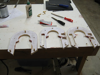
And I cut some bottom pieces. I carefully shaped out one piece to fit and then used it as a template for all the others. Then I sanded the curves onto them on the belt sander. My sander can flip up to 90 degrees so you can set your piece on the table and sand the edges. Very handy feature for this sort of thing. Again, Grizzly tools rock. I got this big ass sander from them several years ago. It's 220 volts, 6 inches wide, and 40 inches long, or something, and it completely rocks. I could grind down a car with it if the need arises. But that also means that I have to be very gentle with fragile plastic pieces like these.


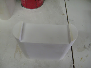
Once I had all the pieces cut, I started gluing. I improved my PVC glue technique a lot here, and killed a lot of brain cells breathing fumes. On the side plates, I cut some 1/2" wide strips and glued them inside with half of them overhanging the edges. This overhang would go over onto the half pipe pieces. Sorry, no picture. That way I had a good gluing surface for the joint, and so that the half pipes and the side plates weren't just butt glued together. I also found that once I had slathered on PVC cement onto one of the gluing surfaces, the trick was to press the two pieces together--not too hard--quickly get them alligned, and then just hold them perfectly still for 20 seconds or so. That let's the cement get an initial setup. I would just lay the pieces aside than and try not to handle them at all for a few hours. The label says that the bond strengthens a lot in 24 hours and that seemed to be right.

Speaking of labels, I a few years ago when I was building something, I had a revelation. This is going to sound stupid--because for 20 years I was stupid about it--but if you just read the damned directions on the label of stuff, or the manufacturer instructions, you'll get a wealth of accurate information that will make the difference between a project that is a failure and one that is a complete success. On the flip side, the place you should not be getting any advice about how to build something is from some snot nosed, dumb ass 17 year old who works at Home Depot and why has never swung a hammer in his life. No offense if you are a snot nosed, 17 year old dumb ass who's never swung a hammer.

And while I am on the topic, the one question that every hardware store employee, lumberyard troll, or counter help asks and that drives me completely insane is, "What's it for?" That is, you come in asking for a piece of foam rubber, or some 1/4" PVC sheet, or, God forbid, a piece of pipe that has an outside diameter of 3", and the first thing they say is "What's it for?", as if whether or not they have will depend on what you're building. I resist the urge to say, "none of your goddamned business," and just try to get them to tell me where it is without my having to explain WHY I am building my own scratch built, fully remote control R2D2. If you tell them that that's why you need the item, they you're less likely to get them to tell you where the pipes are or whatever.

Ok, I'll settle down.


When are started on this phase of the project, I realized that the setup for the battery box parts was most of the battle, and that I could crank out pieces for more of them than I need while I was at it. So at each point, once I was set up I cut enough to make 5 pairs of boxes. I had it in the back of my head that I could sell these to the builder's group if there is interest. I've learned a lot from reading about everyone's experiences and some people might not have some of the tools I have. So email me if you want to buy a pair. I'll have pictures of the end result posted shortly.

A few other notes. As I was designing my cutting plan for the pieces, I tried to build them so that all of the edges that would need to be trimmed would be on the outside, instead of on inside corners. That way, I could easily get to them with the sander and save myself a lot of work.

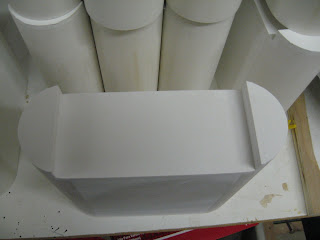
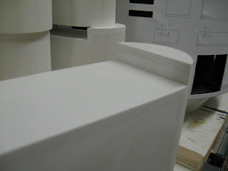
Once all of the pieces--I think there are 14 total--were glued together, I roughed out the curves on the top with the band saw to save my having to sand too much material off. Then I finished the job with the sander. That worked out pretty well. I have started to put primer on one pair and it looks like they'll need a minimum of filling into any gaps between the pieces. More news on those shortly.

I'm looking ahead to building the shells for the outer feet. I got some 1/4" ABS plastic sheeting from Interstate Plastics today (www.Interstateplastics.com). I think that will be sturdier than the expanded cell foam PVC that I used on the center foot.

And I have been reading all the accounts on the web that I can find about the way people have constructed drive systems in the feet. There are some really ingenious systems out there from people with much better engineering skills than me. Jerry Green's drive systems are incredible, and I think they are selling for over a $1,000 now. As usual, Victor Franco and Mike Senna have come up with some really neat solutions to these problems.

Here are some initial thoughts. I think I want to use as much of the full length of the outer feet--14 inches--as I can for a long wheel base for my R2. That is, I want to try to put two wheels into each outer foot, and put them as far apart as I can. I think that will add to stability, and make the unit rock around less when he's moving. I don't want him rattling, bouncing, or tipping. But of course, the shells get shorter as you got out to the edges, so that limits things. For the same reasons, I am wondering about using the widest possible wheels I can find for the job. A lot of the wheels people are using are 5 inches or so high, and maybe only 1.5 inches wide. I am going to try to scrounge up some wider wheels. I would even sacrifice some diameter on the wheels, I think, for some breadth. But maybe someone should argue me out of that. I figure that wide wheels will help make him stable and ride smooth. But I know that bigger diameter will make it easier to get over door sills and things. I'll have to experiment with that, and I'll have to go through the McMaster-Carr catalog.

I'm also wondering about maybe setting the motor up to be direct drive instead of chain drive. But I know that there are serious space limitation issues with the shells and the battery boxes. A lot of builders are hiding their motors inside the battery boxes. I'm not CAD adept, but I am good at intuiting what will work and what won't once I get the materials and parts in front of me and get my hands on them.

I'm also thinking about ways to engineer an aluminum frame for all these motor/wheel/chain contraption that will integrate well with the shells and use the space effectively. Since I am building the shells now, I can design in some features to tie them to the drive train chassis. I am also hoping that I can figure out a way to effectively fabricate/bend/join aluminum. I've learned a lot from Dan Baker's method, and Franco's and others. I'll buy a brake from Harbor Freight tools if I have to, but maybe I can do better. When I roofed and installed gutters and aluminum siding years ago, we always had these big fancy brakes that could put all kinds of complicated bends into the materials. If I could only get my hands on one of those again.

More soon.

MM

Sunday, August 10, 2008

Trickery

Ok droid fans, lots of developments today.

After some trial and error, a couple of false starts, and some cursing, I made some headway fashioning the top of the boot for the center foot today. I cut the trapezoids out of PVC sheet (1/4"). All the angles are complicated. It was probably obvious to someone with more experience reading blueprints than me, but the height measurements given for the feet are for the height of the profile, not the actual height of the pieces. Since the sides of the feet are angled back towards the center, their actual height is taller. Some math with the Pythagorean theorem helped me get the measurements.

Once I had the ziggurat assembly cut and glued up, I came up with this trick to cut the slot through the foot where the connection to the leg will go. I flipped the piece over, set my tablesaw up, and made several passes through to remove the material:


This trick saved me a lot of trouble because calculating the angles and cutting these notches out of the pre-assembly pieces would have been a lot of work. With the saw, it took me 30 seconds to get it all perfect. I also cut it so that the pieces that go in to fill the notch would overlap out onto the face of the foot:


I cut these three pieces a bit long so that once they dried I could sand them down on the belt sander to be exactly flush with the rest of the assembly. If the joints had been on the inside, it would have been a lot of work to get them smooth.

Next, I tried something new with the legs. I want the painted finish on them to be as smooth as possible when I'm done. I don't want any wood grain showing through. So I am trying a coat of grain filler. It's a goopy, wet sort of filler that you wipe on. It fills all the really small crevasses in the grain. That's how they get those mirror finishes on fancy French dining tables. I am hoping that with a coat of this before the primer, I'll get good results. We'll see. I'm sure there are experts out there who could really fill me in on how to do this right:


Next challenge: On the curved and angled pieces towards the bottom of the legs, there is a little slot that is cut out of the angled face. Look here on the real McCoy just above the ankle cylinder:


Getting that little slot cut out has made serious headaches for lots of builders, I think. Here's what I came up with. I have the curved, beveled piece already fashioned out of stacked and sanded MDF. I set up my router table with a 1/4" bit, sticking up about a 1/16" (.060 in the plans, I think.). I flipped the piece over onto the beveled side and ran it all the way through, cutting a groove across the whole face:


Sorry that one's blurry.


But of course, it needs to be a little rectangular inset, not a slot cut across the whole face. So I trimmed down a scrap of MDF to fit snugly into the slot with some extra. I glued those into place carefully to fill in the slot where it is supposed to be flush:


The glue dried fast--it's hot as hell here in Sacramento now. And I carefully put the pieces to the belt sander to trim off any excess and get the pieces down flush. The results were just what I wanted and once their primed and painted, the added pieces won't show:


That's some sneaky ninja shit right there.

Next I have some devious ideas for building the little skirt that goes around the bottom of the feet with all the little rectangles cut out. Coming soon.

MM