Sunday, October 26, 2008

Battery Boxes for Sale


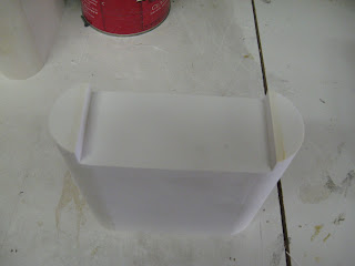
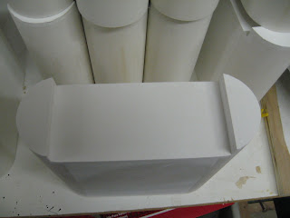
On the last small run of Battery Boxes I did, there was a huge amount of interest. I sold 5 pairs in less than an hour. So I have done another, bigger run. I’ve got 12 pairs to sell.

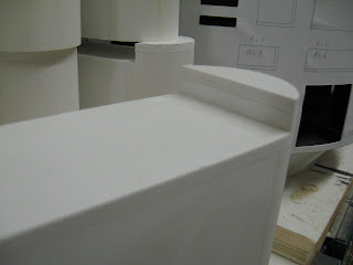
Construction: The side walls, top and bottom are made of expanded cell PVC sheet (1/4”). The end pieces are made of PVC pipe, sliced in half. All joints are glued heavily with PVC cement. They are sturdy enough to stand on.

I have not put any holes in the front for the cables or the sides for mounting to the feet. If you are putting motors inside of them, cutting a hole in them and mounting them shouldn’t be a problem. But I don't know if different motors will be compatible with the 1/4" sidewalls and the reduced width of 2.9". These have not been tested for NPC motors.

Specs: These boxes are to club specifications with one exception. The width of the boxes is about .1" shy of the 3.00" blueprints. PVC pipe with an exact 3" outside diameter is difficult, if not impossible to find.

The inside dimensions are 1/2" smaller than the outside.

Finishing: The boxes have been finish sanded down to 320 grit. All the joints are smooth and clean. They are almost ready for primer. They may need a bit of touch up sanding here or there.

Price: $85 a pair plus shipping. Email me at mccormick@csus.edu for exact shipping costs, and paypal that email address to place your order. I should be able to get them shipped out with a day or two of getting the order.


Monday, October 13, 2008

Ankle Tubes and Shoulder Update


Here are the little tube things that go on each side of the center ankle and on the outer ankles. It took a couple of tries to get them just right, and I am still not perfectly happy with them. But I think once they are painted they'll be fine. I cut 1 inch (inside diameter) pvc pipe to length. Then I cut little squares of 1/8" pvc sheet to glue to the ends. I glued those and let them sit for a few days. PVC cement gets a lot harder if you let it cure for a while. If you sand it too soon, it'll be more flexible and soft than the surrounding material and you'll sand it out of the joint and make a groove.

Once those were cured. I used the sander to round the square pieces down to match the round edge of the pipe. This wasn't a very reliable method for getting them to perfect circles. But I couldn't think of another method that would leave me with no seams.

The little channels that are cut into the circumference of these pipes are supposed to be .03 " wide or so. My table saw blade is .1 so that was too much. My bandsaw blade was just right. I figured out the depth of the channels and put a stop on the crosscutting slider on the bandsaw so that it would stop the piece just after the blade began to cut the pipe. Then I would carefully roll the pipe into the saw blade, keeping the slider still. So it cut a groove all the way around the pipe. This was a reliable and good method with good results. It just took 15 minutes to cut all four pieces and a spare. Then I cut the little hexagonal end caps for the tubes and glued them on. A little more sanding and these will be ready to go.


Here are a couple of pictures of the finished shoulders. I'm pretty happy with these. In an earlier post I detailed how I built up the plywood pattern for these that would guide the router roller bearing as I cut them. I cut all 16 or so pieces, and glued them all together in stacks to make these ribbed assemblies. Then I sanded the outside edges down to clean them up. I spend some time putting putty on the insides of the interior pockets, as you can see, and then routing those on the forms again to clean them up. This wasn't the perfect method. If i was doing these again, I wouldn't cut the interior pockets out at all when I was cutting the individual layers. I would wait until the whole assemblies were glued up and then I would drill a hole in the middle of the pockets, and then rout that out once and all at once. Make sense? That is, instead of routing these pockets out 16 times on each individual layer piece, I would glue them all together and rout them once. Then I'd get really clean aligned inside edges. And there wouldn't be the need for putty. But I think these will clean up for paint just fine. The three dowel holes will get filled later. And I think I'll put some dowels sticking down into the legs for attachments.

Saturday, October 11, 2008

Battery Boxes for Sale


I've got R2D2 Battery Boxes for sale. I have 4 extra pairs. They are constructed from PVC. They are rough sanded and just about ready for primer. They may need a small bit of filler, and some spot sanding. They are to club specs with one minor exception:

Full Disclosure: The boxes are 2.87 inches wide instead of the called for 3.00 inches. PVC pipe with an outside diameter of 3 inches is very difficult to get in the US. But the difference would only by noticeable to someone with calipers and a copy of the blueprints.

They are $75 a pair, plus shipping. I can have the boxed and shipped very quickly. Paypal my email: mccormick@csus.edu. Send me an email with any questions.

Here's a couple more pictures:


Saturday, October 4, 2008

Vacuum Table


I can't see that I'll need a vacuum table, but I might for this project. But my brother is building Snow Trooper armor. So I put this vacuum forming table together for him today. We'll test it out soon.

Monday, September 22, 2008

Shoulders

The last couple of days were spent almost entirely building these:


Here's the idea. The shoulder call for stacks of 8 1/8" pieces with some details and tight tolerances. I bought a sheet of PVC--$50 or so, which is a lot. But I didn't want to do this part in MDF. I think the plastic will give a better, more durable result, especially on the cut edges.

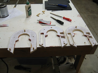
These templates I made by printing up the PDF files in the blueprints to full size. Then I sprayed on some adhesive to 3/4" plywood and laid the plans down on them. The left and right shoulders are mirror images of each other on the cut out details, so I am just going to reverse the template for the other side (I hope I remember to do that when the time comes.)
I worked pretty hard to get all of these cuts just right--there's only an 1/8" difference on the edge alignments. I cut the outside straight edges on the table saw with the fence. That let me get good straight cuts and to carefully control the overall width. To get the rounded curve on the top, I screwed the templates together and sanded them on the 90 degree table on the belt sander. That way they will match.

The inside curve--the round part on the top inside of the horseshoes--proved to be hard to cut. I tried the bandsaw, but mine won't cut curves with that tight of a raidus (3.39" diameter, I think.). Finally I built a little circle cutting jig on my router table. I mounted a piece of plywood over the table, put in a small, straight cutting bit, and them measured from the edge of the bit to the pivot point. I put a pin there, and drilled the exact center of my horseshoe template blanks to accept it. Then cutting the circle was clean and had good results. I think I got well within .005" of the club plans. That's good enough for me.

I've spent the last few days routing, chiseling, and filling in the square cutouts on the sides of the horseshoes. My router chewed up the pieces a bit, so you can see some bondo drying in the boxes here. That'll sand up cleanly.

You can also see some dowel pegs mounted on the templates. I got that idea from Vic Franco. Those will accept my PVC sheets, holding them, while I rout around the template with a flush trim bit. I tried a test piece and the results were very clean, and easy. So I cut a stack of blanks--16 for both shoulders and a few extra--and drilled them to match`the three holes for the dowel mounts. When the templates are done, I'll start cutting and stacking pieces.

Booster Covers


If I had any sense, I'd buy the booster covers in resin for $60 and save myself the work and expense. As it is, I spent a good bit more than that getting a couple of router bits and things to build them myself. But clearly, building your own R2 model isn't about having any sense. So I tackled building the booster covers myself. And I enjoyed it for the most part.

I broke the assembly up into pieces that I figured could be easily cut, finished, and machined. So I made up the legs and the main body piece. And I attached the legs at the end using a separate cross piece. This beats trying to build two legs attached by the small piece at the top all at once. I knew that getting inside to make that little router cut would be hard.

I cut blanks for all piece out of 1/2" fiberboard--again this stuff sucks because of the dust it creates and the cancer it causes. If I did this again I think I'd try to do it in plastic--maybe PVC, although that would be costly.


Once I had the blanks glued up (you can get the fiberboard/MDF in thicker sheets, but this is what I had, and the glue up isn't hard once you get the hang of it), it wasn't very hard to first, cut the bevel cut across the top of them--53 degrees I think, and then I set up the router table to trim that bit out of the inside tops of the legs.


Here's the bigger blank that I made for the thicker top assemblies. The thing looks really complicated on the plans, but it all starts with a simple rectangle. I made extras of both here because it's easy when you're tooled up to crank out another one, and I've learned that having a few extras gives you some breathing room and space for mistakes. I find that when I'm doing a new bit like this, my technique get a lot better after the first one.

Next up, I set up the router with an itty bitty round groove bit, set the fence at the right distance, and set up a stop block on the fence to make sure that I got all of them the same length. Then I ran the legs into the router and put this cute little channels into the bottoms. Pretty easy compared to some stuff so far. The channel groove that goes around the legs horizontally above the vertical round grooves isn't hard with the table saw. I checked my main leg assemblies to make sure that the groove on the legs lines up with the groove on them. Vic Franco said that some of the resin booster covers can heat up and warp out of alignment in the curing process and not line up here.


That smear on the left leg, as far as I can tell, is chocolate ice cream from my two year old who was investigating the work bench. I am hoping it will cover over with paint. When he sees the pieces laying around he shouts, "Doo-Deet, Doo-Deet!" It's pretty cute.


Next up I went to work on the top section of the booster covers. Here you can see the funky curve sanded into the top, the side bevels on the curve, and the pockets in the bottom of the block. Here's what I did. The bevel cuts on the top weren't hard. I measured them off according to the plans, and then I cut them with the bandsaw and sanded them (If memory serves.). Then I marked off the curves on the front and back. The curve is beveled--that is, it doesn't cut through at a 90 degree angle from the front face. I think that some people out there have done this part by using a sanding drum on their drill presses and tilting the table on the drill press. That's a simple and elegant solution. As it turns out, the drum on the end of my belt sander was almost exactly the right diameter for this. So I got the curves marked on the front and back and I very slowly sanded away the material until it matched those lines. Not hard.

I made pockets again by cutting all the way through the block with the router table. I think it's a .3" bit or thereabouts and set to .75" depth. Then I cut some replacement blocks to squeeze down into the channel and leave only the two pockets. Next I'll rout the cove out of this bottom face. The plans call for a 5/8" cove. Bits in that size are hard to find. You can order one, but they are $50 or so. I opted for a 1/2" cove bit which is much cheaper and easier to find. Then I think I'll use a 1 1/4" dowel and some sand paper to remove material to get it to spec. If that proves tedious--and I have a very low threshold for hand sanding tedium--I'll bail and leave it at 1/2" diameter, I think. If anyone has better ideas, I'm all ears.


And here's the whole thing so far laid out, along with the little triangular dog house pieces that sit on top. I made those in box form with 1/4" MDF and then cut and sanded them down to size. It'll take some trimming and detail work to get all of this assembled. But it's close to being done.

Outer Feet Details, Finishing, and Primer


Next step was to fashion the little detail panels that mount along with the half moons on the foot shells. Like many of the other details, I could have bought these. But they were really easy to make. Again I used 1/8" expanded cell PVC sheet, cut the pieces, sanded them a bit, and then mounted them with PVC cement. I did some sanding here and there, a little trimming, and filled a few gaps with some putty, then put on a coat of primer. The results are really starting to look like R2. I'm happy with the feet, and I am happy with the difficult task of getting those bottom skirts with the slots done right. I'll be setting these aside for a while until it's time for more painting.