Tuesday, June 23, 2009

Battery Boxes for Sale, Council Approved.


I have just completed my 3rd run of Battery Boxes. I've got 12 pairs to sell.

Construction: The side walls, top and bottom are made of expanded cell PVC sheet (1/4” and 1/8"). The end pieces are made of PVC pipe, sliced in half. All joints are glued heavily with PVC cement. They are sturdy enough to stand on.

I have not put any holes in the front for the cables or the sides for mounting to the feet. If you are putting motors inside of them, the PVC is easy to work with. You'll have to check to see which motors are compatible with the 1/4" sidewalls and the reduced width of 2.9". I haven't installed NPC motors in these, but some of the previous buyers probably have at this point. I can check.

Specs: These boxes are to club specifications with one exception. The width of the boxes is about .1" shy of the 3.00" blueprints. PVC pipe with an exact 3" outside diameter is difficult, if not impossible to find.


Finishing: The boxes have been finish sanded down to 320 grit. All the joints are smooth and clean. They are almost ready for primer. They may need a bit of touch up sanding here or there.

Price: $85 a pair plus shipping. Email me at mccormick@csus.edu for exact shipping costs, and paypal that email address to place your order. I should be able to get them shipped out with a day or two of getting the order.


Sunday, June 14, 2009

RoboGames--R2D2


Went to the RoboGames in San Francisco today (and the Maker Fair a few weeks back), and hung out with Chris James for a good while. His droid is an amazing piece of work, and his blog has been a huge source of helpful information to me from the start. It was great to get a close up look at it. Chris got me and my boy, Max, into the pit area at the RoboGames by assuring the event staff repeatedly that we were with him. And he even handed me the remote control to drive his R2 around a few times. That showed some trust. I know every bit of agonizing work that has gone into his machine, so I took it very easy.

One Year Progress Report


Despite the lack of activity here on the blog, I've been working on it quite a bit lately. I got the styrene skins all glued on. Getting the inner skin attached to the frame is tricky. Turns out that even though lots of materials experts have opinions about the best adhesive for styrene to wood, none of them seem to know what they're talking about. I bought 15 or 20 different kinds of glue, ran extensive tests on all of them until I found something called Griptonite by Devcon. It's more or less a superglue, but it is a bit thicker than most, and there's something in it that dissolves the styrene a bit to make it bond well. I bought up every tube within a 50 mile radius--TAP Plastics, and attached the inner skin bit by bit. Alignment and drying times were hard, but I got it figured out with some work. Then I got the outer layers glued on. Here I could use standard styrene cement--Testors--and it works fine. The results are good. Here's the whole droid, more or less with a lot of the major assemblies fitted on. I have lots more parts on the bench, but I'm not ready to mount them.

I've also got my Rockler bearing mounted here with the dome ring loose mounted. Lots more work to do. More later.

Wednesday, May 13, 2009

Glue Frenzy

I've been searching all over for some sort of adhesive that will effectively attach my styrene skins to the plywood frame. It's a tricky chemical problem because lots of the glues for plastics work by actually dissolving the plastic itself, so if you are putting to like plastics together, they form a really strong bond. But attaching to wood requires that the glue have some weird hybrid properties. I bought and tried 6-10 different kinds of glues. Nothing seemed to create a sound joint on my test pieces of styrene and plywood. Then I found some stuff that's a variation on super glue. It's by a company called Devcon, and the retail name is Grip-Ton-Ite. I know, the name is so stupid I almost didn't use it. But in the testing, that stuff is creating by far the strongest bond. The plastic broke off before the glue gave up. So that's what I'll try to use to do the inner skins to the plywood frame. Then I'll use some sort of styrene specific glue for the outer skins to the inner skins. That shouldn't be as hard, although I want to be carefully about ooze and spill over. I don't want glue oozing out into all of those carefully cut little channels. We'll see what I can pull off. And I"ll post about the results of the inner skins to the frame as soon as I have made some headway on it. No time with my students all taking finals next week.

Saturday, March 28, 2009

Cleats for the Foot-Ankle Joint


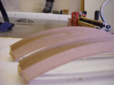
In the beginning, I assumed that I'd want the foot shells to pivot on the legs. It made sense to have him traveling over bumps. But I've rethought that. And I won't be able to pull off any 2-3-2 apparatus. So I am going to build him to be fixed in three leg mode. That left me thinking about a way to join the feet to the legs that was really sturdy and could take some abuse when he rolls around. I was going to put axle pins through the shells into the ankle, but came up with a better idea. I glued up some plywood--stacked to better take the pressure--and cut out these little cleats that will fit in the tracks in the foot shells and around the pointed bottom of the leg. If I had known I would go this route, I would have redrawn the leg patterns to just have this built in. But I'm not going back there at this point. Maybe some day.


Then I carefully drilled some pilot holes up through the cleat and into the legs to accept some hanger bolts. 5/16" by 5 1/2" I think. These are bolts with lag screw threads on one side for wood, and machine threads for a nut and washer on the other.


Yes, that right one is a bit crooked, but that won't matter. Next I lined up these holes to position the foot shell correctly on the leg and then I drilled two holes through the plate inside the groove on the foot shells.


There was some wrangling and cussing, and some redos through all of this, but no more than usual. BTW, I made the template for these little cleats by holding a piece of paper up to the leg (without the foot shell), traced the shape of the leg end, found a level line so that the cleat bottom would be parallel to the floor, and then played around with a mock up shape on the sander until it looked like I wanted. If you are looking for this piece, you can see it. But it's pretty hidden by the leg in the foot shell groove, and once it's primed and painted and finished, it'll look clean and low profile.

I also built some small three sided boxes that would fit up inside the foot shells and wrap around the groove from underneath. My idea was to have the bolts run down from the leg, through the cleat, through the foot shell, and through the inside boxes. Then with some nuts and washers, the whole assembly could be cranked down together. I figured that this layered design would add a lot of rigidity and strength to the whole bottom end. And the boxes can now have some bolts sticking down to bolt on a wheel and motor assembly that can be easily taken off. Pictures help:


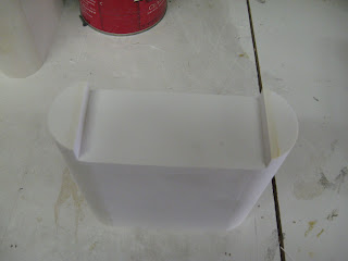
In this next picture, the foot shell is flipped upside down and the inside box has been drilled and put inside. Then I drilled these and pushed the whole thing up onto the bolts that come down from the legs. Some nuts and washers snug it all up.


Then end result is not so impressive from the outside. But the joint is really solid now. There's minimal flex or torque. And I will be able to easily mount a wheel assembly onto the boxes inside.


It's really appealing to manufacture an aluminum assembly like Mike Senna and Vic Franco have done on there's. I like that design they've come up with. But I was looking at their materials list and all of the special order aluminum channel, thinking about the expense, and hesitating to use my good wood working tools and blades to cut aluminum. Then it occurred to me that I could probably make a very similar foot motor assembly to theirs out of wood. I'll still have to buy wheels, axles, motors and all of that. But the flexibility of this method is great for me. And it cost me nothing since I used scraps of plywood from around the shop. The hanger bolts cost $4--btw, Orchard Supply Hardware has big ones. Home Depot sucks and does not. Lowe's sucks less, but doesn't have them either.

Large Data Port


There are good, inexpensive resin data ports for R2 available from resinparts.com, but I figured I would take a crack at making my own. I'm pretty happy with the results although the angles and dimensions aren't quite in the tight range that I want. I reserve the right to change these out later with better ones.

I used MDF. I think a 1/8" piece and a 1/4" piece. First I cut the circles to the right diameter with the circle jig on my bandsaw--same method I used to cut the rings for the frame way back at the beginning. I had to do some calculating and wrangling, but I figured out the angles of the bevels on the rings and adjusted some dimensions to make it fit well in my frame. Then I cut the bevels with the circle jig on my bandsaw and using the tilting table. That gave me clean cuts and even bevels. Some minor sanding smoothed out the edges. The little end pieces were easy to cut and glue. A coat of primer, some sanding, and then finish coats should make these look just fine.

I've gotten in the habit now of making an extra of everything as long as I'm all tooled up to cut the pieces. That gives me some slack and some room to screw up.


Tuesday, January 27, 2009

Rough Attachments for Some Leg Details


At this point, I have gathered—either scratch built, or bought—almost all of the detail parts for the legs. My plan is to get the legs fully rough assembled before starting to do finish sanding, filling, priming, and painting. I’m going to attach the shoulder horseshoes by epoxy-ing some short dowels into the mounting holes left from when I cut them. Here I’ve drilled matching holes into the legs and you can see the horseshoes placed temporarily on the legs. It’s cool to see these parts come together. And it surprising how instantly recognizable it all is, even at this very rough stage. But then again, for those of us who’ve spent too much time analyzing every frame of the movies are going to have some strange sensitivities. I have also located the shoulder hydraulic units inside their pockets on the shoulders. I drilled pilot holes (carefully) into the back of the hydraulic units and matching pilot holes with counter sinks on the back side into the backs of the shoulder. Then I put some tiny screws through to hold the hydraulics in place. When it comes time to attach these permanently, I’ll probably epoxy and screw them on. I suspect that heating and cooling and getting banged around could make a lot of these little parts work their way loose if they aren’t substantially attached.


I’ve also drilled out some dowel holes in the backs of the booster covers and matching holes in the body of the legs. So the booster covers will be pegged down to the legs after painting with glue too. It took some measuring and some filing to get all the holes lined up and they are still a bit too tight, but it’s getting there. The booster covers are still a bit rough and need some filling and sanding.

The boosters that I got in resin don’t fit well inside the little angled dog house. I put the calipers on them and it looks like they are out about .05. But that’s enough to make trouble. I will probably trim the insides of the covers and sand the boosters a bit too for a good fit.

And I have attached one of the battery boxes here (the one that can't be seen in these pictures). I made key hole slots in the insides of the boxes and mount small screws in the foot shells to hold them on. That won’t be a long term solution, but it’ll hold them on there for the moment. I suspect that when I get done cutting and fitting with the motors for the feet, the attachment for the battery boxes will have to be moved and changed to something bounce proof.