Showing posts with label legs. Show all posts

Sunday, December 6, 2009

Legs Finished!

I did the final things on the list today to the legs. Yesterday I had dabbed a bit of touch up body filler--the Bondo kind in a tube, it's petroleum based, so it dries with air contact-into a lot of little flaws revealed by the first coat of primer. Today it just took a few minutes to sand those down flush with some 320 and 400 grit paper. Then I vacuumed the legs thoroughly and took them outside for another coat of primer. The temp was probably around 50 degrees, which is just at the bottom of the operating range for that spray paint. But primer is pretty forgiving. The second coat went on without any real problems and these are ready to go now:


This is the whole package for the builder who commissioned these from me. I'd probably put a coat of black paint on the hubs if they were going in my droid. I'm happy with the results:


The only remaining flaws at this point are very small and will be covered by paint. The next steps would be to add a few more coats of primer with some very light sanding--maybe with 00 or 0000 steel wool in between--then several light coats of a gloss white with some light sanding in between the early ones.

What did I learn this time through:
I got the high end baltic birch 12 ply plywood. It's very good, stable, and straight. But the outermost layer, the layer that will end up showing to the eye, is fragile. Home Depot and Lowe's usually have some good 12 ply cabinet grade plywood, and I have found that the outer layer on that stuff is a bit thicker and a bit more sturdy. I'd go with that next time. I'd also cut a 3" circle out of the insider layer of the legs at the top where the shoulder hub is going to sit, although the router method I used yesterday wasn't too bad. The router method for cutting the pockets out under the shoulders is a very clever idea I got from Mike Senna through Victor Franco. The best way was to have a couple, but not all, of the layers glued, and then rout out the pockets with a template from the inside. Each leg weighs several pounds. I think that next time, I could rout out a lot of material on the insides of the pieces without compromising the strength at all. The ankles could have a lot of interior material removed, the channel for the wiring could be wider, and the shoulders could be more hollow. That could save a pound or two per leg, and that would add up. The modification to the center leg tip to make a better connection to the foot shell is an improvement. Next time, if I was setting up a fixed three legged droid, I think I'll work out the plans to do that on all three legs--building the ankle locks into the design.

Sunday, November 29, 2009

Legs 7: Getting Close

I set up the table saw yesterday to make a very shallow cut around the body of the legs. There's a detail there on R2D2 that needed to be added. I've tried to get a good picture of it several times, but no luck. My camera doesn't do extreme closeups very well. I set the saw blade to run .06" high (yes, that is possible), and then after carefully measuring the location, I ran the legs through so that there was a groove that runs all the way around:

The tape helps prevent blowout with the outer layer of the plywood.


I also finished gluing the curved pieces to the center legs:


Then I cleaned the excess glue up off of those, and used the orbital sander to bring down the edges of the MDF pieces where they overlapped. I got the MDF pieces all sanded flush and incorporated. I also put a 1/2" axle hole in them. Be sure to clamp a scrap to the back side when you drill to prevent blowout. The center legs are almost finished. I'll go over them once more for any gaps or dings that need to be filled, fill them, finish sand, and then I'll put a coat of primer on them to see to what extent any seems or joints are showing through. You can also see the modification on the tip of the leg here. This extra wing will rest down flush into the foot shell groove and provide a stable joint between leg and foot. And since this is on the back of the leg, it would still be possible to straighten this leg up for an upright posture:


I also finished gluing and nailing the four ankle panels to the bottom of each leg. And today I cleaned up the glue and then sanded the sides on the belt sander to get a good clean joint.


Once that was done, I could finally lay out the lines for the leg tip:


I roughed those cuts in on the band saw.


And then finished them down close on the belt sander with the belt tipped up to 90 degrees. The end results are starting to look familiar:


So what remains is to mount those curved pieces on the right onto the ankles, cut the round hole into the shoulders for the shoulder detail, and then do some finish filling and sanding.

One problem I've been having is blowout on the the outer finish layer of the plywood. I don't know if I got a sheet that had too little glue in the final layer or if the final layer is just too thin, but some spots are really fragile and friable. The worst example is when I made this cut through with the band saw:


It all blew off of there so suddenly an severely that I have to think that they messed up on the glue here. But I'm not sure. This sucks as it produces a lot more work for me and it lowers my confidence about the rest of the pieces enduring use over the long term. I have a couple of options to fix it (the other spots are much less bad than this). I can try to fill the region in with glue, body putty, or fiberglass/resin Bondo and then sand it in to blend. I think the last option will make the best looking and most durable results. I'll work on that this week. I also think that once I get some primer on there to seal these up, and then their new owners get several more coats of primer and several finish coats of paint, that paint will cure and form a consolidated skin that will be more durable. The wood won't do this once it's painted right. But I have to be extra careful until then.

Thursday, November 19, 2009

Legs 2

Following Mike Senna's method here, the legs will be built up out of 5 pieces of plywood. The rough arrangement looks like this:

That's two pieces of the 7/16" on each side, and a piece of 11/16" in the middle. This configuration comes the closest using standard dimensional lumber to getting all of the thicknesses and measurements exactly like on the club plans. I think there are a couple of spots where this arrangement comes out to be .1" thicker or thinner than club specs. That's a minor variation I can live with, and when these are done no one would ever be able to find it unless they got calipers out and check the plans on every dimension. In my experience, many of the aluminum parts--the gold standard, as it were--for the club are actually out at least this much or more from the plans. One way to address that, if you were so inclined, would be to either run a couple of these pieces through a thickness planer and shave off a bit, or do it manually with a belt sander.

When they are all stacked, the configuration will look like this:


I'll make a suggestion here on the method that a lot of builders are using. It's tempting to cut each one of these plies out exactly to fit its pattern on the plans and then try to line them up and glue them together. Almost inevitably, that produces some misalignments. Once you get a layer of glue in there, its usually not perfectly evenly distributed. Then it's very hard to get the clamps distributed evenly and get the clamping pressure exactly even. So pieces will shift laterally a bit as the glue sets and glue will accumulate more in some spots and less in others. Then the resulting misalignments on the sides produce a whole bunch of clean up work. It'll take sanding, filing, lots of Bondo, and some tendonitis to get the sides all clean and even again.

The answer is to glue the blanks together first, and then make the cuts through the whole stack of pieces second wherever possible. That way the glue is set and the cut will make a nice clean side that will require minimal Bondo and sanding work.

That's going to be hard in any situation where there's an inside corner edge, of course. I'll document how I'm going to deal with that in coming posts.

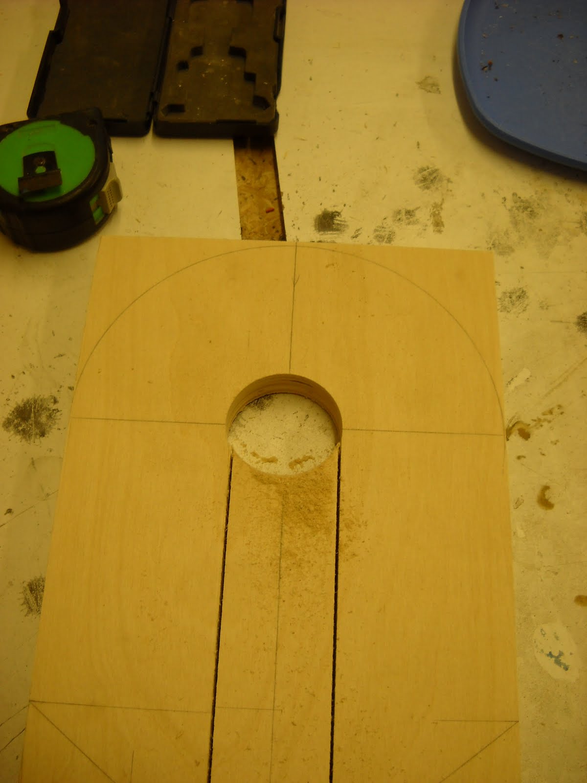
Meanwhile, the center ply, the piece of 11/16", needs to have a channel down the middle of it for wiring to go to the feet. I've set up on the band saw for this with a stop block at the end of the cut. Whenever you are cutting a lot of parts--I'm making two sets of legs here--set up a stop block on the saw fence so that you can run all the pieces through to it. That insures uniform cuts on all pieces, and it's faster than measuring and marking every piece.


Then I used a 2 1/8" hole saw to take the middle piece out. This circle is centered on the same radius that the outside of the shoulders will be. I'll put another circle through the next inboard ply to open the channel.


Next up, I laid out four holes to accept T-nuts that will be embedded in this piece. These will provide the mounting for the legs through the shoulder hubs and into the body. The configuration of these bolts will be different for you depending on which frame design you settle on.


Notice also that I have made a counter sink for the T nuts with a 1" paddle bit first, then I drilled the 1/2" hole for the body of the T nut. This is important because you want the T nut to sit down flush or lower than the surrounding plywood. Otherwise, when you go to glue another piece on top, the T nut will prevent the next piece from laying down flush and tight.

This method of attaching the legs introduces some tight tolerances on the bolts. The bolts will be coming out from the inside of the frame and into this T nut. If the bolts then go through and past the T nut too far, they will push the outer ply of the glued up legs out and possibly crack and separate the laminates of the legs. I have put a shallow dimple in the next piece that goes on top of these to make for a bit more room, but these are only 1/4" or so:


But the depth problem with the bolts shouldn't be too hard to deal with. Once the legs are all assembled, I can put a small rod down in these holes and see how much depth there is. Then you can measure the distance from the inside wall of the mounting plates in the frame out to the outside edge of the shoulder hubs. Add those two numbers, and subtract 1/4" or so for some leeway, and you'll have the length of the bolts you need measuring them without the bolt heads. Also take into account space for a big fender washer on the inside. If this length doesn't match a manufactured length, get the next size up and cut them off or add washers, etc.

Next up, I'll be gluing up the layers. An important trick for getting them aligned and clamped. Don't just glue and clamp. Line the pieces up dry first, clamp them, and then put some screws through them (but not all the way through to the front face:


These screws will act to align the pieces and prevent the drift during gluing that I discussed earlier. They they will help give some even clamping pressure. And they will significantly increase the strength of the glued joint. In fact, when joints are done like this, the resulting bond turns out to be far stronger than the surrounding wood. The wood will fail before the glue does.

Thursday, August 7, 2008

Leg Axle

I pondered how to attach the legs for a long time. I finally settled on a method not far from Victor Franco's and Mike Senna's. I rummaged around at Home Depot and found pipes and fittings that would let me have a 3/4' diameter pipe on one side, mounted to the leg with a floor flange, and a slightly larger pipe on the other side that would fit over the 3/4" pipe inside the R2. I routed out the inside surfaces of the legs to hide the floor flanges, and did some cursing and grinding on the two pipes to get a nice fit. But eventually I got the legs to fit onto the body.


You can see the two pipes coming together inside the frame here. You can also see the big round plugs that I built as mounts that go between the legs and the upright plates in the body. I had to trim the tops and one is rotated down in the picture. Nothing is secured here--I was just checking for fit.


I'll attach the mounting plugs with screws from the inside, and I'll put a pin through a hole drilled through both pipes inside the body, as Senna and Franco suggest. That'll allow me to take the legs off later if I need to disassemble the droid for transport or something.

One problem that I haven't read about solving by anyone is how to set up this axle or the legs so that they do not rotate past the 18 degree angle that they are supposed to form from the body when R2 is in the 3 legged position. I can imagine several ways to do it.

If you're going to go for the full 2-3-2, fully automatic and motorized R2 function, then this will be solved other ways. If you're building a fixed, three legged R2, then you'll just screw the legs into the back, locked position. I am not going to have full 2-3-2 auto function--that's too hard to do with so much wood, and without a full machine shop. But I think I would like to have the option of putting him up into the upright 2 legged position manually for pictures or display, or whatever. (It does worry me how unstable he must be in that position.) So I'd like to do both. Right now I'm thinking that I'll put a pin through the frame, the mounting block and into (but not through) the shoulder of the leg from the inside. That'll hold the leg in position. Then if I want to change it, I'll pull the pin, move the legs, and put the pins into another set of holes. But I'll have to think about it.


You can also see that I've screwed the skirt onto the frame here. I'll glue a piece of white styrene onto the bottom of the frame, between the frame and skirt eventually. The underside isn't very visible, but I want to have some nice, clean finishing details there when I'm done.

Leg Glue Up

I was anxious to get the leg pieces all glued up. Before I was committed to having them together, though, I wanted to do any work on the individual pieces that might save me headaches later. This means the little cut outs in the arm pits, right below the shoulders. There's just no easy way to do this, but cutting the inner piece of plywood before it was glued helped. Then I traced that outline onto the outer and inner pieces of plywood, and chiseled the material out to spec with my mortiser, and a some work with a sharp chisel and hammer. Some putty, sanding, trimming, and carving got the whole little pocket into pretty good shape before the glue up. Sorry no pictures of this part. Email me for more details.

A few tricks to share about the gluing process. First, when you glue pieces of wood together and clamp them under pressure, then tend to drift and slide around on each other, messing up your alignment of the edges. I glued two pieces at a time. While they were dry, I would clamp them together aligned exactly right. Then I would put a screw through the two pieces from the inside where it wouldn't show. Then I'd unclamp them, take out the screws, glue them, and put them back together. Then I"d put the screws back in carefully so that they went right back into the original holes. That way when I started clamping, the screws would keep the alignment perfect. If you've ever tried to desperately keep drifting pieces aligned while glue quickly dries, you'll see what a huge labor saver this is. In some cases where nothing could show, I would put a blind pin in between the two pieces by cutting the head off of a little finish nail, drill a little hole in one board, and then pressing other one onto it while keeping them aligned. This way there's no screw head showing. Sorry no pictures.

I think the tendency for a lot of people is to over clamp wood pieces. A couple of things. First, get an nice even thin coat of glue on both pieces to be glued. You want a small bead of glue to ooze out of the sides when they are clamped and drying. A lot of clamping pressure isn't needed. You'll drive all of the glue out of the joint and weaken the bond. Let the glue, not the clamps, do the work. Second, use some scrap pieces of wood under the clamp heads to prevent marring of your surfaces. If you do put a clamp dent in it, you can wet the dent thoroughly and then gently iron it with a hot iron. The water in the wood fibers will expand and the dent will swell back out. You'll be amazed at how big a repair you can do this way. Third, put the clamps on one at a time on opposite sides and slowly start to build up even pressure across the whole pieces. You can never have enough clamps. Get a bunch, and evenly distribute them around the edges. Put some newspaper underneath for the drips.

When the glue is about half way dry---about an hour for many wood glues and depending on the heat and conditions--you can gently scrape off the oozing drips on the edges with a chisel. It'll be clean and easy if you wait till then instead of doing it while the glue is runny. Sorry no pictures here either.